Due to various compounding personal reasons I was not able to winterize my house in time this year. Usually I do this some time in November, before much snow has fallen so it is still accessible by car. It is a process that involves draining the water system and setting a thermostat to keep the basement from freezing. I got delayed until December 16th which means over half a meter of snow had already fallen. This meant I had to resort to skis to access my house and do the winterization. Luckily temperatures in the basement hadn't fallen below 2°C despite the delay.

The distance from my house to my neighbor is 300 meters and takes around 20 minutes by skis, 45 minutes with snow shoes. Not the greatest thing to be forced to do. I therefore took the opportunity to install a thermostat that can be controlled remotely. Since I know quite a bit of electronics and how to do computer stuff this felt like a perfect less-than-a-week project. The result is shown in the two pictures below:
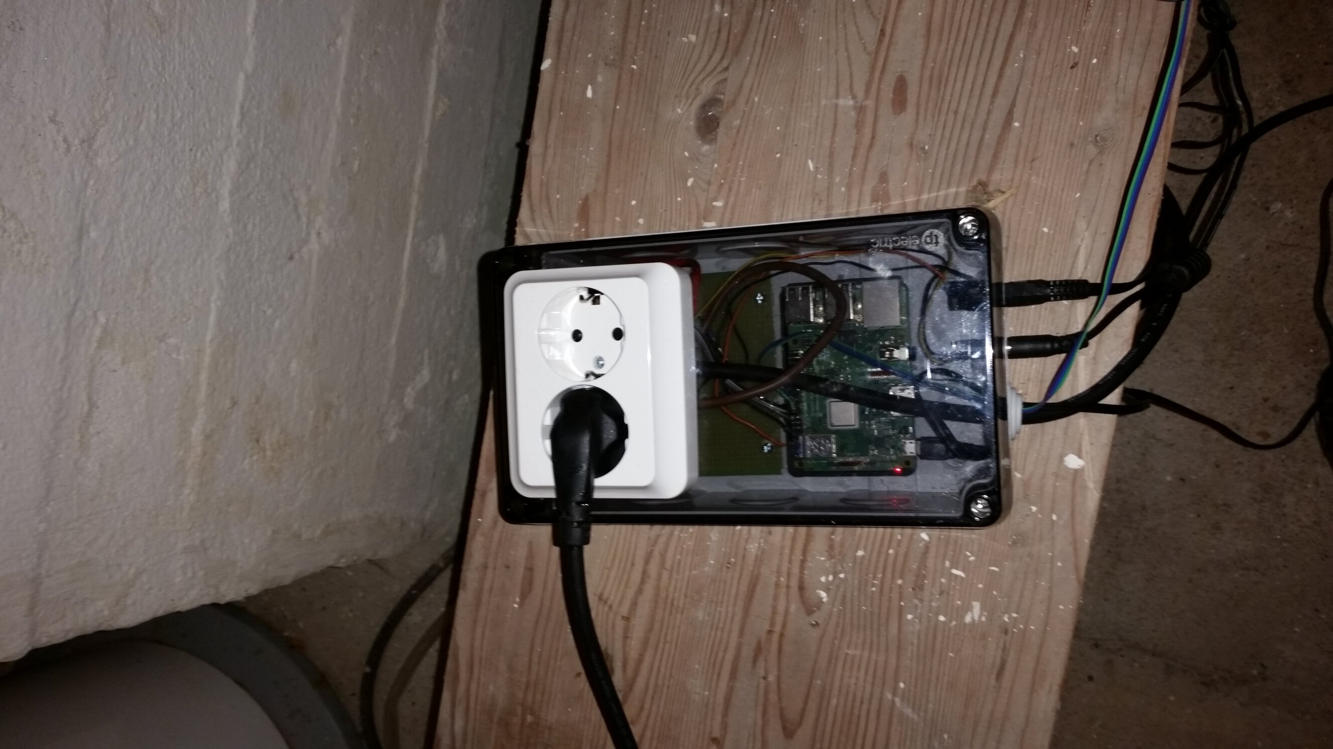
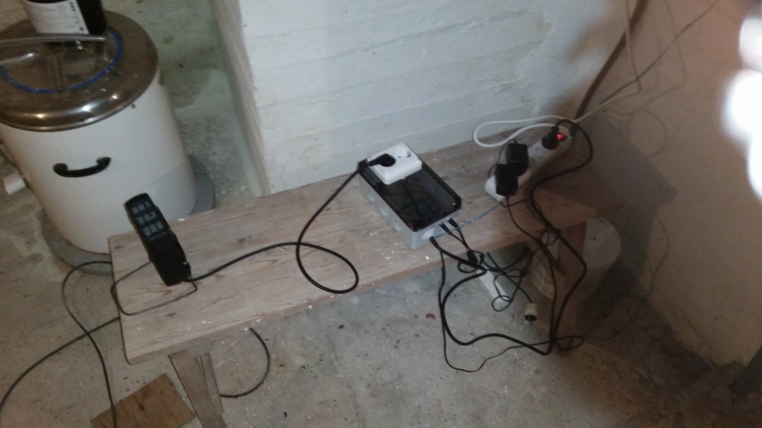
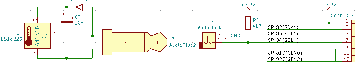
A heater is connected to a box which has a wall socket on it and a Raspberry Pi and some relays inside. A schematic is shown below:
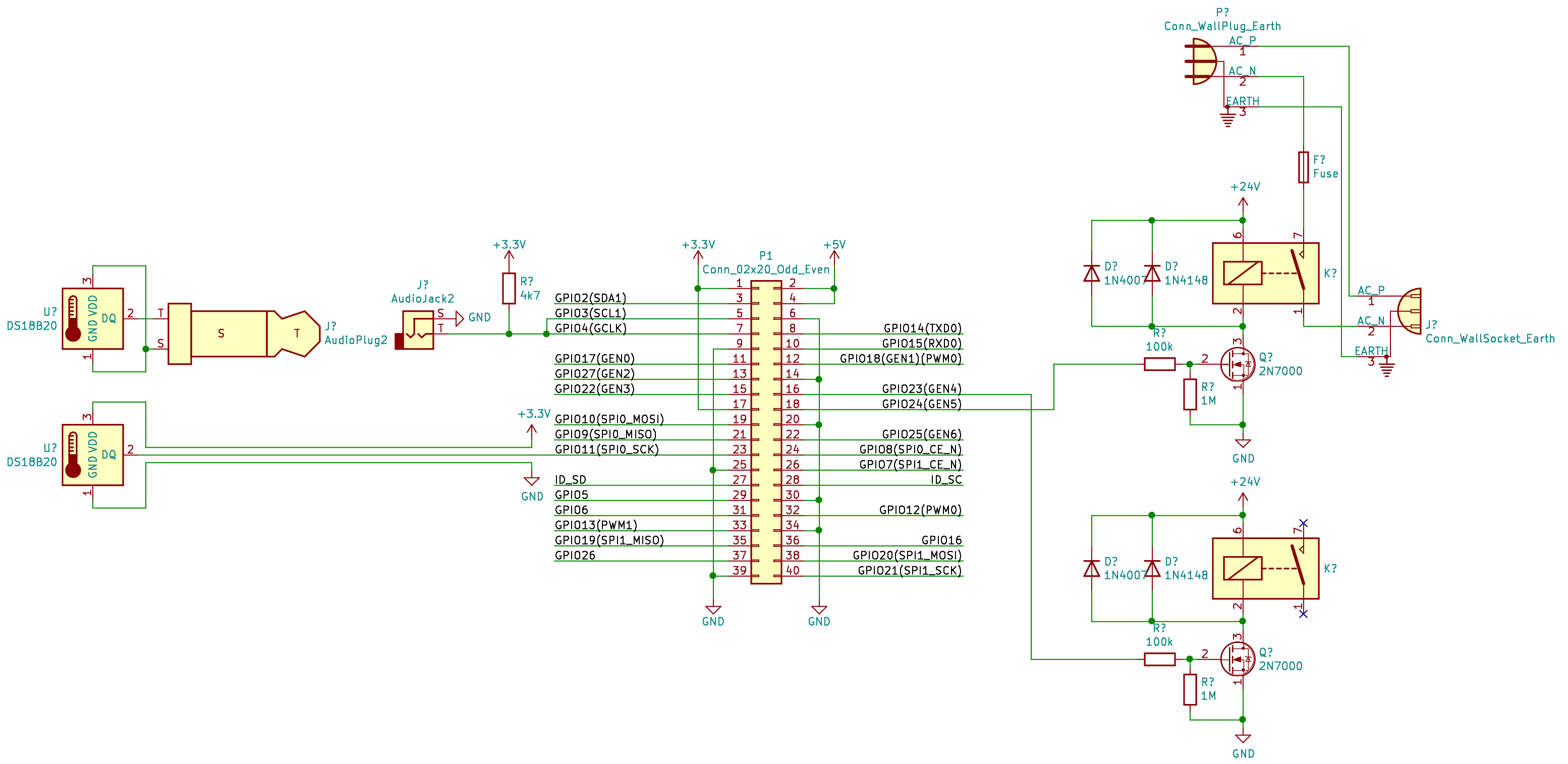
Both relays use 24 V coils and are capable of switching 16 A 230 VAC. 24 V is given by a wall wart. I use both a 1N4148 and a 1N4007 as freewheeling diodes to get both quick switching and higher current handling capability. It is likely overkill but doesn't hurt.
The circuit board that the relays are soldered to has had copper drilled away in relevant places to improve isolation. In addition the 100 kΩ resistors in series with each MOSFET gate provide extra protection. Only one relay is used at the moment.
I have two 1-Wire DS18B20 temperature sensors connected. One sensor is connected via a 3.5 mm mono (TS) phone jack and the other is connected directly via a 3-wire ribbon cable. I had initially wanted to use parasitically powered sensors but there is currently some kind of bug with the Pi's 1-Wire driver that makes this unreliable. More on that later.
The Pi is connected to the WiFi in my house and can be logged into over SSH by jumping via two other machines. I hope to reduce this to just one intermediate machine in the future.
Control, minimizing electricity cost
One thing that a computerized and internet connected thermostat enables is better temperature control. Especially with how high electricity prices are at the moment, I want to run the heater when the electricity is the cheapest. Such information is provided by Nord Pool, via a public API for dayahead electricity prices.
Given a thermal model of the basement, optimal heater control can be realized given dayahead prices and the weather forecast. Doing so involves solving a linear program on the form "minimize cost subject to basement temperature ≥ 4°C". This program can then be re-formulated and re-solved every hour, yielding desired heater power. It is tempting to think one should just run the highest power heater at full blast when the electricity is cheapest, but higher basement temperature also means higher thermal leakage. There is likely an optimal solution between this extreme and just setting a constant thermostat set point.
Currently I have the heater configured to run a bit warmer between 22:00-06:00 on the assumption that electricity is reasonably cheap during these off-hours. The current setting is +9°C during these hours vs +5°C the rest of the day, with +-1°C hysteresis.
Besides the above, one problem with my current setup is the limited thermal inertia available. I only have the air as a thermal mass besides the basement itself, and the basement's concrete walls conduct heat away relatively quickly. I'd prefer something like a sand "battery" that is heated up at optimal times. Another possibility is to run the water heater since it's already available and water is a good thermal mass. Whichever mass is used, they provide a "buffer" between heater power applied, the basement's air + water pipes and the walls of the basement. They therefore allow moving closer to the "max power at the cheapest hour" mode of heating.
Based on statistics over the years I know that roughly 10 kWh/day is necessary to keep the basement above 4°C. I may write a post in the future diving further into this once I have more statistics.
Code
The following Python program is used to control the relay.
It is executed by the pi user on startup by adding the following with crontab -e:
@reboot /usr/bin/python /home/pi/thermostat.py
And the code itself:
#!/usr/bin/env python
from gpiozero import LED
from time import sleep, time, localtime
from os.path import exists

relay_lower = LED(23)
relay_upper = LED(24)
relay = relay_upper
relay.off()
on = None
csv = open('/home/pi/thermostat_log.csv', 'a')

def get_temp():
 filenames = [
  '/sys/bus/w1/devices/28-000008d67211/w1_slave', # trs
  '/sys/bus/w1/devices/28-000008d6526e/w1_slave', # backup
 ]
 for filename in filenames:
  if exists(filename):
   # read temperature
   with open(filename, 'r') as f:
    t = float(f.readlines()[1].split(' ')[9].strip().split('=')[1])/1000
    return t
 raise Exception('No DS18B20')

def set_relay(state, t):
 global on
 global csv

 if on != state:
  on = state
  if state:
   relay.on()
  else:
   relay.off()
  csv.write('%f,%.3f,%i\n' % (time(), t, int(state)))
  csv.flush()

# returns (t_on, t_off)
def limits_per_hour(hour):
 cheap_hours = [22,23,0,1,2,3,4,5]
 if hour in cheap_hours:
  return (8, 10)
 else:
  return (4, 6)

t = get_temp()
set_relay(False, t)

try:
 while True:
  try:
      t = get_temp()
      t_on, t_off = limits_per_hour(localtime().tm_hour)
      #print(t_on, t_off, t)
      if t >= 85:
       # sensor is broken
       continue
      elif (t_on < t_off and t > t_off) or (t_on >= t_off and t < t_off):
       set_relay(False, t)
      elif (t_on < t_off and t < t_on ) or (t_on >= t_off and t > t_on):
       set_relay(True, t)
  except Exception as e:
   print('Exception: ' + str(e))
   set_relay(False, t)
   sleep(60)
except Exception as e:
 set_relay(False, t)
 raise e
except KeyboardInterrupt as e:
 set_relay(False, t)
 raise e
The above code will need adapting to your own situation, especially the sensor filenames.
1-Wire over phone connectors
There is no official specification for 1-Wire connectors, less so for 1-Wire over phone connectors. There is a semi-official RJ-11 standard documented here. There is also a proposed phone connector standard here but it suffers from not being usable with mono connectors for parasitically powered devices. The table below describes what I think would be a sensible standard:
Mono (TS) | Stereo (TRS) | TRRS | |
|---|---|---|---|
| Tip | DQ | DQ | DQ |
| Ring | VCC | VCC | |
| Ring | Interrupt | ||
| Sleeve | GND | GND | GND |
We can see that the above proposal uses a mono plug for parasitically powered 1-wire devices and a stereo plug for cases where VCC is required, and a TRRS connector when interrupt is available.
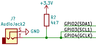
Currently the Raspberry Pi 1-wire driver does not appear to follow Maxim's specifications when it comes to parasitically powered devices. When using devices that draw considerable power such as the DS18B20 during temperature conversion, the DQ line should be tied to VCC during the conversion. In fact it appears best to connect DQ to VCC whenever no communication is being done. This is the reason why many users only get a +85°C reading. Web searching "raspberry pi 1-wire t=85000" gives lots of hits relating to this issue. Somehow I got parasitic power to work by connecting GPIO3 and GPIO4 together.
Ways to get get parasitically powered 1-Wire to work on the Raspberry Pi
The DS18B20 datasheet states that the device uses ~1 mA (1.5 mA max) during temperature conversions, which takes between 93.75 to 750 ms depending on resolution. A minimum of 3.0 V is required. The device accepts 5 V but the Raspberry Pi's GPIO pins do not. Finally the DS18B20 is guaranteed to be able to sink at least 4 mA.
Most of these methods have not been tested yet.
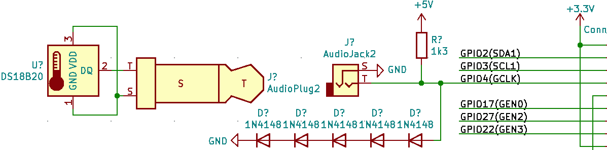
5 V DQ, lower pullup resistance and Zener
The DQ line can be driven at 5 V which is readily available on the Raspberry Pi's GPIO header. With a 1.3 kΩ pullup resistor then DQ will drop no lower than 3.05 V during temperature conversion. 5 V / 1.3 kΩ = 3.85 mA which the device is perfectly capable of sinking. One might be tempted to think the Pi's GPIO pins can deal with 5 V through a resistor since the pins are capable of sinking up to 16 mA (source). But this does not apply to the protection diodes. A Zener diode or five 1N4148's in series can be used instead.
Capacitor buffered VCC
A diode and a capacitor can be used to feed VCC. A limitation to this approach is that the capacitor must be allowed to recharge between conversions. Its voltage must not drop below 3.0 V during conversion. Assuming the charge on the capacitor is 3.2 V then its capacitance must be at least . The pullup resistor can be as low as . The time necessary to recharge the capacitor is therefore . If the standard 4.7 kΩ resistor and a more available 10 mF capacitor are used, then the time comes to . The is due to 3.2 V being three times "closer" to 3.3 V than 3.0 V is.
I have not taken the voltage drop across the diode into account here. As the capacitor gets close to fully charge the current across the diode drops and therefore also its forward voltage drop. The diode drop is logarithmic in the current, , so charging the capacitor to 3.2 V likely takes longer than calculated here. Experimentation is required. A Schottky diode would likely be more appropriate than a 1N4148.
Connect GPIO3 to GPIO4
This is what I did. I'm not sure why it works, but it does. Possibly because pullup is enabled on GPIO3 which supplies just enough extra current for everything to work.
I am not sure how reliable this is, so for now I am using the sensor connected with three wires. I did not have any TRS jacks on hand, only TS, hence a direct cable connection rather than some nice connectors.
Lower pullup resistance
As shown above, as little as 825 Ω should still work. During conversion DQ may drop as low as 2.06 V. While this is lower than the minimal voltage specified, the charge stored inside the sensor may be enough to make up the difference, especially when using lower resolution. The datasheet unfortunately does not specify the value of Cpp.
Fixing the driver
The w1 driver appears to be a binary blob, so I'm not sure if it can be patched. But if it can, then I would suggest that the GPIO pin output logic high when not communicating with any device. The GPIO pins are able to supply more than sufficient current for the job.